 Vietnamese
 English

The concept of mechanical drawings
Mechanical processing drawings are an important means in the field of processing; used to present and transmit information about the design, dimensions, shape, location, and other specifications of a mechanical product.
Mechanical drawings play an important role in ensuring the quality of the final product, fully meeting the set technical requirements and standards.
During the design and manufacturing process, design software such as AutoCAD helps mechanical engineers create accurate 2D and 3D engineering drawings, thereby ensuring accuracy and standard proportions in the manufacturing process.
To grasp and understand what the drawing represents, we need to know the symbols in mechanical engineering drawings.
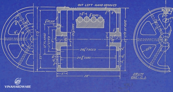
Detailed technical drawings of the machine
Lines and strokes of 2D drawings
In mechanical 2D drawings, detailed product lines play an extremely important role to be able to visualize or properly interpret the actual design of the processed product. Here are the basic lines:

Detailed product lines
Surface roughness
As a concept in the field of mechanical engineering and manufacturing, refers to the properties of the outer surface of a material or product. Surface roughness determines how smooth and glossy a surface is after being machined or fabricated. It affects many important factors such as friction, accuracy, performance, and aesthetics of the product.
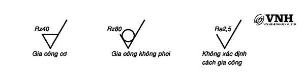
Symbols and grades for surface roughness rating
There are several common surface roughness ratings and ratings used. Example:
- Rz: Represents the error in 5 points on rough or semi-fine surfaces (e.g. turning, milling, etc.). This is a common measure in evaluating roughness.
- Out: Represents the average undulation of the surface after being machined by grinding methods.
Geometric error
Tolerance in machining is the allowable fluctuation between the size, shape or position of parts in a product compared to specifications previously defined during the design process.
Miền dung sai được lựa chọn phải cân nhắc kỹ lưỡng để đảm bảo sự cân đối giữa độ chính xác và khả năng gia công. Ngược lại, nếu miền dung sai quá lỏng lẻo, sản phẩm cuối cùng có thể không đáp ứng được yêu cầu về chất lượng, ảnh hưởng tiêu cực đến độ tin cậy và hiệu suất của sản phẩm. Dung sai được ký hiệu trong bản vẽ cơ khí như sau:

Ký hiệu dung sai theo quy ước JIS - Nhật Bản
Ngoài ra, để đọc và hiểu được ký hiệu dung sai trong bản vẽ cơ khí chế tạo máy cần chúng ta cần phải hiểu về các loại dung sai:
| Loại | Đặc Tính | Ký Hiệu | Đối tượng chọn làm chuẩn | Định nghĩa |
| Hình Dạng Dung Sai |
Độ Thẳng của đường thẳng |
 |
- | Tính trên 1 độ dài nào đó và được đo với đơn vị là mm. |
|
Độ thẳng của mặt thẳng |
 |
- | Độ phẳng của mặt phẳng là độ lệch lớn nhất giữ 2 điểm trên cùng 1 mặt phẳng. | |
| Độ Tròn |  |
- | Độ lệch tính trên đường tròn với đơn vị đo là mm. | |
| Độ Trụ |  |
- | Độ lệch tính trên mặt trụ với độ dài nhất định. | |
|
Độ lệch của cung tròn |
 |
- | Độ lệch tính trên 1 dây cung | |
|
Độ lệch của bề mặt cung trụ tròn |
 |
- | Độ lệch tính trên bề mặt 1 cung trụ với độ cao nhất định của trụ | |
| Shape tolerances |
Độ song song |
 |
Có | Độ lệch giữa 2 đối tượng là đường thẳng song song hoặc nằm trên quỹ đạo là đường thẳng song song |
| Perpendicularity |  |
Have | Deviation between 2 perpendicular lines when compared to 2 absolutely imaginary perpendicular lines. | |
| Angular Deviation |  |
Have | Deviation in angle | |
| Circular arc deviation |  |
Have | Used for different circular arcs | |
| Bow surface deviation |  |
Have | Use for different surfaces | |
| Position tolerance | Position deviation |  |
Yes & no | Deflection of hole positions, hole center |
| Concentricity |  |
Have | Roundness of the circle | |
| Coaxiality | Have | concentricity of 2-axis or 2-hole | ||
| Symmetry |  |
Have | Deviation between 2 symmetrical faces versus true symmetry | |
|
Deviation of Round arc |
|
Have | Measure the deviation to the top position of 1 circular arc | |
|
Deviation of bow surface |
|
Have | Measurement of deviations in position on the circular arc surface | |
| Surface inversion tolerances | The reversal of the cylindrical face relative to the centerline |  |
Have | The radial reversal of a cylinder with respect to some nominal/standard cylindrical centerline is measured over a cross section |
| Head reversal relative to the centerline |  |
Have | The head reversal for the center line or centerline of some standard pillar mite is measured on the boundary of the head circle |
The application of reasonable tolerances in mechanical processing is an important factor to ensure efficient production and processing. This strikes a balance between precision and machinability, thereby ensuring the final product fully meets the requirements for quality and reliability. Vinahardware (VNH) understands and applies tolerance symbols in mechanical drawings to help ensure the accuracy and aesthetics of products. With the application of the most modern equipment, Vinahardware (VNH) is proud to provide customers with detailed and fast mechanical processing services at reasonable prices.
Tuan Anh -VNH

